Invention of the Mechanical Explosive Igniter

It’s been a while since my last post – other things have had my attention. A reader, John C, responded to a post I wrote last year with some thoughts and this encouraged me to look again at this fascinating and crucially important piece of (explosive) history.

This then is a follow up to this post   which I suggest you read through to refresh your memory. In it I explore some interesting technological developments regarding the development of explosive initiators in the early 1500s.  Why is this important?

    1. Until the early 1500s, explosives (gunpowder) could only be initiated by the physical application of fire. Gunpowder was initiated by applying a burning match to a small quantity of gunpowder which then ignited a larger charge, whether that be inside a gun or inside a larger container.
    2. Effectively this limited the use of explosives/gunpowder, because a prior step was needed to ignite a match and keep it burning until such time as it could be used.  This limited how explosive devices or firearms could be used, slowing the process or making it more obvious. So the technology development described below allows for speed of action, timeliness and concealment – all important characteristics of explosive devices.
    3. The invention of a mechanical igniter gave much more flexibility and did away with the need for a burning match. Devices could be placed, concealed and left. Firearms could be concealed.  Devices or firearms could also be initiated almost exactly when needed rather than after a delay.
    4. Mechanical igniters such as this enabled booby traps (Victim operated devices) (perhaps with a trip wire), enabled command operated explosive devices (via a pull string) and even enabled timed explosive devices (where a clock hand could pull a string). As far as firearms are concerned the jump from matchlock to wheel-lock is a very significant technological leap.

So in the history of firearms and in the linked history of explosives (as the site purports to be, in a sense)  these mechanical devices described in my earlier post are quite significant.

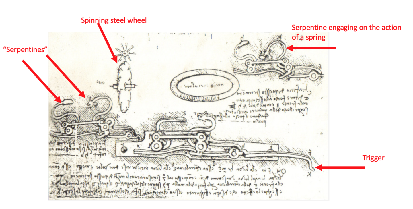
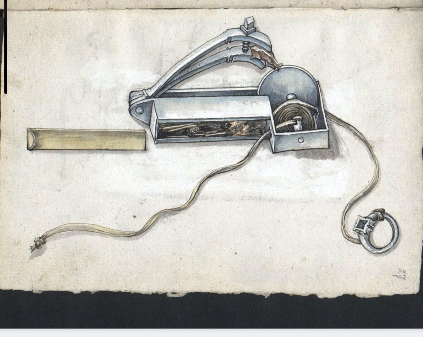
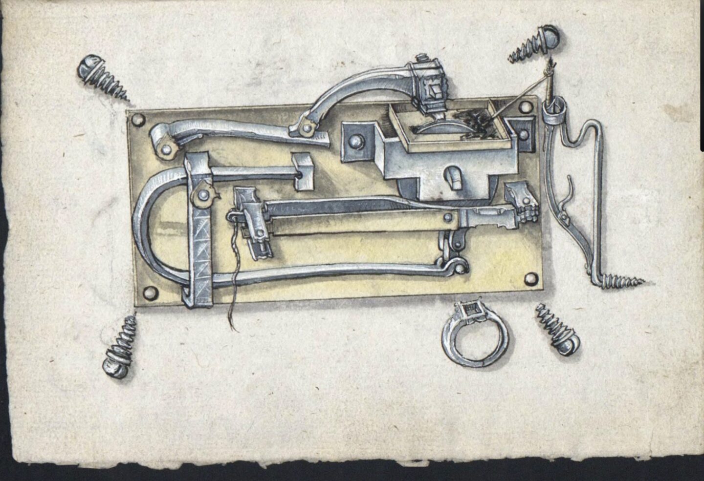
In the earlier post last year I included a copy of beautiful diagram of a mechanical igniter from a date of about 1505. Historically speaking this is technically a wheel lock but I think was invented before a similar device was fitted to a hand held firearm. It’s maybe the first wheel lock mechanism.  This device and one or two others were carefully drawn and included in the“Loffelholz Kodex”. At the time I hadn’t worked out how this igniter had functioned. I’ve now spent some time scratching my head and doing a little research and I think I may have an answer. But I’m only about 60% certain, so if you think I’m wrong, please correct me. I’m very open to alternative interpretations of this intriguing machine.  For ease of explanation I have included the diagram again here below but with some annotations.

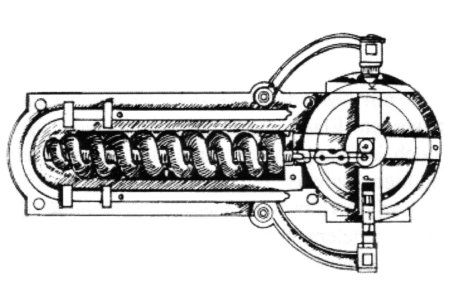
I originally thought the device had a coiled spring hidden behind the wheel (F) to cause it to turn, but I no longer think that is true. Importantly I don’t think coiled springs of the type I had envisioned had been invented at this time.  Rather, like the simpler device seen in the last post, there is a cord wrapped around the wheel’s axle. The horizontal J shaped main spring (B) has its longest arm, along the bottom and this is the spring which pulls the cord down, causing the wheel to spin. The wheel is prevented from turning by the Brake (C) in the middle to which a pull string is attached. Pulling that away from the wheel is like releasing a parking brake. In normal conditions this Brake (C) is held in place by the brass bar running in parallel to it acting as a spring.  The bit I’m slightly unsure of is the Cord tensioner (G). This holds the cord tight against the axle. You can see the finger holder that you pull when winding up the wheel(F) with the winding key (E).

So… let me describe the preparation and action…

1. The winding cord is tied to the end of the J shaped main spring and the other end to to the right hand contraption. The right hand contraption is tensioned using the finger guard to pull the cord.
2. The wheel is turned using the “ring key”. This causes the cord to wrap around the axle of the wheel. (Somehow!)
3. As this is done the J spring is flexed upwards, and held there by the cord.
4. The “brake” acting on the wheel prevents the tension of the cord to act on the wheel. .
5. After a few turns the brake is engaged, holding the wheel.
6. The tray is primed with gunpowder or tinder.

The action on firing is as follows:

1. At the chosen time the string is pulled.
2. This pulls the brake away from the wheel.
3. The J spring now acts pulling the cord down that is wrapped around the wheel’s axle.
4. The wheel rotates
5. The serpentine holds the pyrites against the rotating wheel
6. Sparks are generated and thrown into the gunpowder/tinder in the tray. The ignition of this gunpowder or tinder can then be used to ignite the main charge though some sort of channel.

I’m not quite sure about how the cord is wrapped on the axle – this important component is hidden from view.

The Loffelholz Codex was produced at roughly the same time as Leonardo da Vinci was also developing spring powered wheel locks. Frankly his diagrams are much harder to interpret that these in the Loffelholz. I have no idea which came first, and it doesn’t really matter perhaps. Other technologies which enabled this design include:

    1. Metallurgy and the ability to produce, shape and utilise Spring steel, which seems to have occurred in the late 1400s.
    2. Clock technology, and associate manufacture of relatively carefully produced metal components.

The impact of this development was significant – in 1512 such mechanisms were banned in at least one European country because of the capabilities it provides to those with nefarious intent, and therefore a threat to society of the time. There are interesting parallels with trying to control and constrain explosive technology today.  Wheel locks continued to evolve into neater, smaller designs designed to be mounted on or built in to firearms, usually with some clever spring design – but this early example is entirely separate from a firearm in this form.

More early explosive ROVs

In an earlier post here, I discussed some First World War antecedents of modern ROVs, these early one being used to deliver explosive charges – essentially a mobile land mine.  One of the early ones I mentioned was a Schneider “Crocodile” from 1915 which I have not much information on but is pictured here, and which apparently was French developed, but was trialled by a number of nations including Britain and Russia.

Here’s a pic of the controlling team, manning some sort of command interface while the ROV pays out or pulls a cable. I think they are French.

Interestingly I’ve just come across a reference to a number of other Russian devices, some of which seem to have been ROVs. These are referred to as “Sidelnikov’s mobile mine, the creeping mines of Kanushkin and Doroshin, the crocodile mine of Colonel Tolkushin.”     It’s interesting that Colonel Tolkushin’s device was also called a “Crocodile” like the French device. I have only this poor image of it from about 1915-1920:

It seems to be a multi-charge device, on wheels, but to be honest it’s not that clear. Alas my Russian is not good enough to dig out more detail.

Russian ROV technology also preceded some other German technology to deliver large explosive charges in WW2 that I have written about here .  In the 1930s, Russia developed the “Teletank” . One of the versions of this teletank had a large charge (200-700kg) which was “dropped” by the ROV tank like the German Borgward. These were radio-controlled tanks and utilised some early systems which were designed to prevent radio jamming.  Don’t underestimate Russian technology.


Goliath – a Revisionist Historical Anomaly

An odd little historical wrinkle I have uncovered – bear with me.

The development of EOD remote control vehicles by the British Ministry of Defence in the early 1970s is the stuff of legend. Like many legends the story was probably more complicated and nuanced than many history books show. It was reported then, and to a degree now, as a piece of British ingenuity defeating dastardly terrorism.  While I don’t doubt the innovative and remarkable efforts of a number of people in this process, it always struck me as a little odd that the history of the “wheelbarrow” RCVs in the early 1970s is presented as emerging solely from the imagination of a handful of key people, with no reference to the decades  of RCV development that preceded the 1970s. Indeed I have written extensively earlier on this site about RCVs developed in WW1 and WW2, including quite a bit about the German demolition RCV “Goliath” used extensively in WW2 by the Wehrmacht.

Here’s a couple of my posts about early RCVs. linked:

GERMAN WW2 USE OF ROVS TO DELIVER EXPLOSIVES
HISTORICAL ROVS

And here’s a picture of the German “Goliath” of WW2. Note the “rhomboidal” track configuration.

I was therefore intrigued when reading a UK MoD history of the development of “Wheelbarrow” EOD RCV to see that the Mk 4 Wheelbarrow, introduced in the first part of 1973, had a rhomboidal track configuration.  I don’t think any Mk4 wheelbarrows survived, and it is a little known chassis variant – the Mk 4 and Mk5 were very similar with the Mk 5 seeing extensive use.  The Mk 3 version was usually fitted to run on wheels but some were designed with tracks in a rhomboidal configuration and these developed into the Mk 4.  In fact I hadn’t seen the rhomboidal track configuration on the Mk 3 or Mk 4 and had assumed it had the same configuration as the Mk 5 which had a rear track configuration that was “round” around the drive wheel.  It’s important to note that these early British wheelbarrows were used to deliver explosive charges as often as they were used to deliver disabling tools.

I was therefore struck to find a press cutting from 1973, referring to a bomb disposal RCV, I believe a Mk 4 wheelbarrow, in Northern Ireland, showing the rhomboidal track configuration. Not only that, but the RCV is referred to as “Goliath”. That can’t be a coincidence. Clearly someone at least recognised the similarity of the track configuration between the wheelbarrow Mk 4 and the German WW2 RCV. How strange. Could the German Goliath similarity be more than coincidence?  Could the design have incorporated aspects of the German Goliath design from 30 years earlier?  It appears that the name “Goliath” was quickly taken “out of use” perhaps because it would have been seen as inappropriate in 1973 to refer to some sort of Nazi provenance for the design of this proud “British” piece of equipment.

Here’s the press clipping – note the design of the tracks and compare to the German “Goliath” above.


So, there are three possibilities:

  1. The similarity between the German Goliath -and the British Goliath (now officially a Mk 4 wheelbarrow) is entirely coincidental, despite both being designed to deliver explosive charges over difficult terrain..
  2. That someone noticed the coincidence, called the 1973 equipment “Goliath ” in a “tip of the hat” to the German equipment of WW2, and later that name was wiped from history, for embarrassment.
  3. That it was more than coincidence and the British designers examined and perhaps copied parts of the design of the German Goliath as they constructed the Mk3 and Mk 4 wheelbarrows. The name was ‘carried over” but later squashed as in 1973 it was a better story to tell of British ingenuity, rather than British reverse engineering a Nazi piece of equipment.

As a reminder,  WW2 German Goliaths were battery powered like the Wheelbarrow, only later versions being converted to run a small internal combustion engine.

Tell me what you think.  I mean no disrespect to those hard working engineers within the UK MOD who provided EOD teams in Northern Ireland with these remarkable tools in quite stunningly short timescales. I’m simply trying to place the RCV development of the 1970s in a broader historical context, if that’s where it fits. I can find no mention in the official history of such a link.


Explosive Devices on the Moon.

It may seem bizarre, but Rocket Propelled Grenades were taken to the moon on a couple of the Apollo missions to the moon in the 1970s. Three were fired, and five were abandoned.  So there is an interesting EOD task outstanding on someone’s operational docket for a future mission.    This is the surprising story.

One of the ambitions of the Apollo project was to understand the geology of the Moon. Accordingly, a number of passive and active seismic experiments were planned.  The active seismic experiments were mounted during Apollo 14 , Apollo 16 and Apollo 17. The active component of the experiments on Apollo 14 and 16 had two parts. Both involved placing ground sensors and then using explosives to create a shock waves.  The first experiment was relatively small scale, using a hand-held “thumper” which fired small cartridges to impart a small shock wave to the surface of the moon, which were then detected by the sensors. It is the second experiment that I find more interesting however.  For this experiment a number of rocket propelled explosive devices containing varying amounts of explosives were used, and the launch initiation was radio-controlled, with the impact causing the detonation when they struck the moon. In much of the documentation the system is called a mortar but elsewhere the charges are referred to as rocket propelled charges or grenades. It’s semantics, and doesn’t really matter.  But what they were innovative and relatively complex explosive charges designed to be launched by radio signal from a baseplate, and impact the moon surface some distance away, detonating to send a distant shockwave back to the sensors.

It’s worth considering the fundamental differences that launching a rocket/mortar/grenade provides on the surface of the moon that don’t occur on the surface of the earth.  There is no atmosphere so there is no need to streamline the projectile. Also there is only a fraction of the gravity.  So trajectory calculations are very different and hence design parameters of the munition quite different. Calculating the range tables would have taken some interesting but not difficult calculations.

As far as I can make out the grenade launcher/mortar system was identical on both Apollo 14 and 16. The four explosive devices on each system were set to fly 150, 300 900 and 1500m but the explosive charge was not the same across the four projectiles – but rose with the range. The explosive charge weights of the grenades were 0.1, 0.3. 0.6 and 1.0 lbs of explosive consecutively. Unsurprisingly, there were multiple safety mechanisms in the systems and the experiment was designed to be initiated by earth-bound technicians and scientists after the astronauts had departed back to Earth. So the astronauts’ job was to set the ground sensors, put the launch system in place and level it appropriately and then “stand well back” by a few million miles.

For the Apollo 14 mission the launcher was placed in a sub-optimal position due to a crater, and the experiment was abandoned because of concerns that the dust from launch of the projectiles would cover other experiments.  This surprises me since  the lunar module itself contained a much bigger rocket and surely threw its own dust much more widely.  So there are four unarmed, unfired explosive projectiles sat in launch tubes near the Apollo 14 landing site waiting for some EOD operator to sort them out. Good luck with that.

For the Apollo 16 mission, although there were problems setting up the launcher, the system was fired, launching three of the four projectiles. On the launch of the third device, the base plate tipped over so the fourth remained unlaunched. Our intrepid Space Force EOD operator of the future should consider carefully the arming state of this abandoned device.  Not a place you want to have an ammunition incident.

The design of the mortars and associated system is particulate interesting technically. I have covered the varying charge weights above. Clearly it was important to know the velocity of the projectile after launch and this was calculated by a a 25ft stainless steel break-wire line with a copper electrical cables wrapped around that which was attached to the projectile and which broke after launch, one immediately and one at 25 ft allowing its velocity to be calculated. The angle and pitch of the launching platform was also recorded, and also on each projectile there was a radio device transmitting the time of flight.  So the angles, speed at launch and the time of flight of each missile were were all known. Quite a complicated little munition with interesting safety features. The calculated range was expected to be accurate with 5%. Each grenade was less than 3 inches across and the larger devices about 6 inches long, the smaller 4 inches long.  They were mounted on the base plate in a bank of 4.  Here’s a circuit diagram of the grenade, which shows some interesting design features – including a spring loaded blanking plate isolating the detonator from the main charge.  This steel plate is ejected by the action of the spring as the explosive device leaves the tube, allowing direct passage from the detonator to the main charge and also releasing a safety microswitch. Some of you will have seen bore-constrained spring-actuated safety measures on some earth bound systems.   There was an omni-directional impact sensor to cause the detonation and a thermal battery to power both the 30 Mhz transmitter and the initiation system.

The mortars were designed to be launched at 45 degrees.  The rocket motor is very short duration, and indeed is designed to have been fully burnt-out at less than 10 milliseconds, before the device has left the launch tube – another reason for the vagueness in terming this a rocket or a mortar, but note that this is fired basically from a tube that is open ended at both ends, making this in my mind a rocket propelled grenade, nonetheless. I think this was chosen (rather than a closed tube mortar) to make an overall lighter system.

I jumped up to the moon last week and managed to get this X-ray of the Apollo 14 system ;- )


All this is useful information for our imaginary space-suited EOD operator. I think the answer is “blow in place”.  :- ).   I understand that the 3 grenades that functioned provided useful results and the shockwaves of their detonation were detected.

Apollo 17 also used eight radio controlled explosive charges (these not intended to be launched but placed) to conduct seismic experiments. These were small 57 g charges that were detonated by radio control when the astronauts were halfway back to earth, and had been manually placed at distances away from the landing site and the sensors.


Development of Mechanical Explosive Initiators in the early 16th Century

A few days of enforced idleness has given me a little space to think. Inspired by my (off topic) recent post, a book review on the evolution of piston engines in the Second World War I’ve been thinking again about key technological developments in history with regard to explosives and related issues.

To put this blog into context, let me try to make things really simple.  An explosion, (whether that be of high explosives or gunpowder) is a chemical reaction, typically a change from a solid to a lot of gas. For about 500 years from about 1000 AD to 1500AD, there was only gunpowder, a low explosive, and this mix of chemical solids could be brought to change to gaseous products with the application of a naked flame which starts essentially a combustion process.  So by introducing a naked flame, or equivalent amount of heat, it starts the reaction, and causes the explosion of hot gases. Until about 1500 the only way of igniting gunpowder was by heat or flame. You can see my earlier post about other related technologies here.

But having to have an already burning flame or equivalent is tricky. You can’t disguise it easily. If your “match” is unlit you have too start a fire somehow and that takes time, even more so before the age of boxes of matches and cigarette lighters.  All this led to practical challenges in the use of firearms and explosives.  The most efficient method until 1500 (and indeed for many years later) was to have ready a slow match burning well in advance,

The time was ripe then in 1500 for a more flexible way of initiating gunpowder, either in a firearm or for an explosive device or indeed nay kind of munition that used gunpowder.  There then appears to have been a key turning point enabled by a number of disparate technologies. These include:

  • Engineering skill in terms of precision craftsmanship from clock makers. This included the development of skill which creation of relatively fine metal components that could be shaped into a fair amount of detail.
  • Advances in metallurgy and associated engineering that led to effective steel springs.  The springs become a “store” of energy which can be released to cause sparks with a little ingenuity. To be effective, springs needs to be relatively high in carbon so they don’t lose their “springiness”.   In the century running up to 1500, the manufacture of springs became optimised.
  • To me  (as an amateur blacksmith) there appears to be some clear links and cross over between “door lock” mechanisms that use springs to release levers, and these gun lock systems. As I understand it these engineering developments were also occurring at about this time in history.  And of course the word “lock” crosses the gap – in German where these may have been invented the word used for both firearm locks and gun locks is “Schloss”.

Around 1500 the wheel lock was developed, perhaps in Germany or perhaps by Leonardo Da Vinci.  The mechanism of the wheel lock is that potential energy is stored in a spring.  When the spring (carbon steel enabled by metallurgy) is released, this spring (a coil)  typically causes a steel wheel to turn around a spindle as in clock technology. The wheel , with a jagged edge turns against a quantity of pyrites, causing sparks to occur. The sparks drop into a container of ignitable material, typically gunpowder in our case.  In preparation to ignition a key is used to tension the spring, which is held on a latch.  That spring can be held indefinitely, with only the release of a latch needed to initiate the mechanism and whatever combustible is placed next to it. When the latch is released by a trigger, the wheel spins and another spring loaded lever pushes the pyrites into contact with it. Interestingly the “wheel” also needs to ideally be carbon steel to get the best sparks, so the development of these two key components were driven by clock makers developing springs for their mechanisms using carbon steel, and understanding how energy could be released from a spring and applied usefully. After all, engineering is often about how energy is turned from one form to another.

I’ve written before about a lovely diagram from the 1580s of an IED initiated by a wheel lock , with a fantastic picture I found in a book in the British Library. That post is here, but I’ll repeat this diagram below for convenience – it’s one of my favourite historical IEDs. One doesn’t need to understand the writing to work out what’s going on – note the string attached to the trigger, the wheelock mechanism and the fuze leading to a barrel of gunpowder.

So this image was a wheel lock initiated IED from 1582, and I wanted to find an earlier example.  Some sources suggest that Leonardo Da Vinci was the “inventor”, so I’ve been hunting for Da Vinci diagrams.  Here, below, is one from the “Madrid Codex” . Whether Da Vinci actually designed this or was simply copying a design made by a German inventor is an issue for the academics. If I’m honest I can’t quite understand the diagram (and also the accompanying text!)  but I have picked out some key points.  Let me at least point these out to you:

  1. The Trigger, is at the lower right hand side.  Compare this with the trigger above at the top, tied to a piece of string which runs round a pulley.
  2. There are two Serpentines in the diagram below. A serpentine is best thought of as a lever which acts under the effect of a spring. If I’m honest I’m not certain of the purpose of the left hand one – it could be as a release-latch on the spring loaded steel spinning wheel.  The right hand serpentine I think holds the pyrites, and a spring action pushes that down when triggered. “Serpentines” were of course used before wheel locks to hold the burning fuze of a match lock, then press it into the gunpowder when a trigger was pulled releasing it. the second serpentine could though, be a failsafe, duplicate to the first.
  3. The spinning wheel is shown vertical and isolated but I suspect it was horizontal, but it’s not clear to me how this was held. I’m also not sure what the circular object in the middle is.


In doing some more digging I found a couple more interesting diagrams that are worth showing in the context that I think they may not be to ignite explosives, but rather to light tinder, which in effect meets the same requirement.  Perhaps these “mechanical tinder igniters” were precursors to the wheel lock. They date from the first decade of the 1500s, right in the early days of match locks and I have lifted them from the “Loffelholz Kodex”. Here’s the first:

This is really a beautiful diagram, from 1505, and I think shows a pocket-sized igniter. A portable “everyday carry” from 500 years ago.  The box container contains tinder” or , if you like, gunpowder. The brass slide holds the tinder in a box. A cord is fitted to a spindle, and wound round and round. Also attached to the spindle is a steel wheel, and the serpentine holds the pyrites. The user, with a ring on his finger to which is tied the cord, pulls, the wheel spins, the pyrites is engaged , sparks fly and light the tinder. Replace the tinder with gunpowder, and run the cord as a trip wire and you have a booby trap IED.  You can see that with the addition of a clock spring ,  a release catch to allow the spring to act on the wheel and another spring to engage the pyrites, it is the same idea.

The second diagram is more complicated, and I confess I can’t quite work it out. But it is clearly a wheel lock device for some purpose or other. If you can interpret the action here, please let me know your thoughts. I can see the “wheel”, the tinder box, the serpentine holding the pyrites and one , if not two triggers, but I can’t quite work out the springs.  Clearly this is meant to be screwed onto the side of something.

What these inventions do, that previously wasn’t very easy to achieve, are:

  1. Reliable ignition of gunpowder without the need for a pre-lit burning fuze, allowing concealment in advance. This is a key IED capability. Previously any emplaced device would have been spotted by the smoke emitting from a match, and could not have been left for any length of time.
  2. Booby trap initiation – using the “string” to release a spring, or pull a spindle, both causing sparks and thence initiation of a charge.
  3. Command initiation from a distance, again using the string.
  4. Timed initiation – because a clock could be used to to cause the trigger to be pulled – and it was clock engineers who were developing the mechanisms anyway.

So these are startling new offensive capabilities for explosive devices. As such, the development of the wheel lock had perhaps more of an impact on explosive device design than on firearms. where , in battle at least, the need to conceal a burning match was not an issue.  Perhaps there was an impact though on the use of firearms in ambushes and for highway robbers, when firearms could be concealed under a cloak. Such mechanisms in firearms were quickly banned in some countries – again showing the potential for the illicit use of a mechanism such as this for nefarious effect.

As such I think that historically speaking the development of the wheel lock is one of the most significant engineering developments in the history of explosives as it provided several distance new IED capabilities.     Wheel locks were expensive to produce so the use of match locks continued for some time – flintlocks which came some time later were simpler and therefore cheaper to produce, eventually phasing out the wheel lock.  That development is in itself interesting because it was a “simpler” technology replacing a complex engineered device.

Before I finish, there’s two interesting aside. Most wheel locks used a concentric spiral spring to turn a spindle that ran through its middle. But there’s two other initiating systems , one a variant of the spring construction. This is it below, another Da Vinci Drawng, this from the Codex Alantic and you can see that the spring is a longitudinal coil rather than a spiral, but it still acts on a “wheel” that is perpendicular to the length of the spring.

Finally another approach to the same problems this not using a wheel at all but a longitudinal bar of steel pulled so that it scrapes along the pyrites. This is the Monk’s Gun, held in the Dresden Armoury. This dates from somewhere between 1480 and 1550.

Although it has no “wheel” it has the advantage (?) of being somewhat simpler. You can see the “serpentine” holing the pyrites, and the ring on the bottom is pulled to the right, causing the teeth on a steel slide to act on the pyrites producing a spark – hidden behind would have been a touch hole leading to the chamber of this simple gun.


Close Me
Looking for Something?
Search:
Post Categories: