Goliath – a Revisionist Historical Anomaly

An odd little historical wrinkle I have uncovered – bear with me.

The development of EOD remote control vehicles by the British Ministry of Defence in the early 1970s is the stuff of legend. Like many legends the story was probably more complicated and nuanced than many history books show. It was reported then, and to a degree now, as a piece of British ingenuity defeating dastardly terrorism.  While I don’t doubt the innovative and remarkable efforts of a number of people in this process, it always struck me as a little odd that the history of the “wheelbarrow” RCVs in the early 1970s is presented as emerging solely from the imagination of a handful of key people, with no reference to the decades  of RCV development that preceded the 1970s. Indeed I have written extensively earlier on this site about RCVs developed in WW1 and WW2, including quite a bit about the German demolition RCV “Goliath” used extensively in WW2 by the Wehrmacht.

Here’s a couple of my posts about early RCVs. linked:

GERMAN WW2 USE OF ROVS TO DELIVER EXPLOSIVES
HISTORICAL ROVS

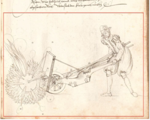
And here’s a picture of the German “Goliath” of WW2. Note the “rhomboidal” track configuration.

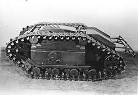
I was therefore intrigued when reading a UK MoD history of the development of “Wheelbarrow” EOD RCV to see that the Mk 4 Wheelbarrow, introduced in the first part of 1973, had a rhomboidal track configuration.  I don’t think any Mk4 wheelbarrows survived, and it is a little known chassis variant – the Mk 4 and Mk5 were very similar with the Mk 5 seeing extensive use.  The Mk 3 version was usually fitted to run on wheels but some were designed with tracks in a rhomboidal configuration and these developed into the Mk 4.  In fact I hadn’t seen the rhomboidal track configuration on the Mk 3 or Mk 4 and had assumed it had the same configuration as the Mk 5 which had a rear track configuration that was “round” around the drive wheel.  It’s important to note that these early British wheelbarrows were used to deliver explosive charges as often as they were used to deliver disabling tools.

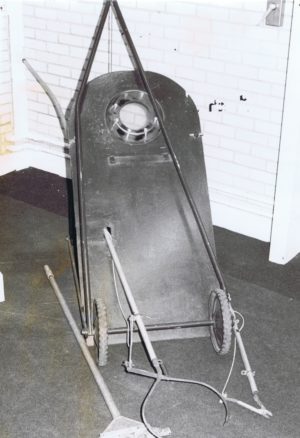
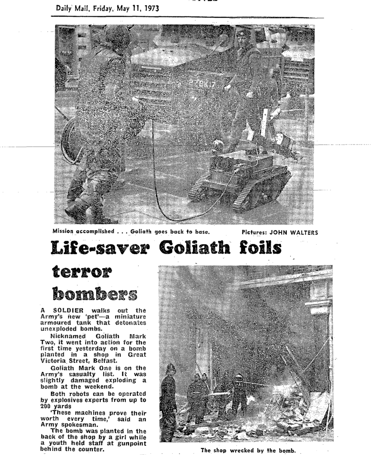
I was therefore struck to find a press cutting from 1973, referring to a bomb disposal RCV, I believe a Mk 4 wheelbarrow, in Northern Ireland, showing the rhomboidal track configuration. Not only that, but the RCV is referred to as “Goliath”. That can’t be a coincidence. Clearly someone at least recognised the similarity of the track configuration between the wheelbarrow Mk 4 and the German WW2 RCV. How strange. Could the German Goliath similarity be more than coincidence?  Could the design have incorporated aspects of the German Goliath design from 30 years earlier?  It appears that the name “Goliath” was quickly taken “out of use” perhaps because it would have been seen as inappropriate in 1973 to refer to some sort of Nazi provenance for the design of this proud “British” piece of equipment.

Here’s the press clipping – note the design of the tracks and compare to the German “Goliath” above.


So, there are three possibilities:

  1. The similarity between the German Goliath -and the British Goliath (now officially a Mk 4 wheelbarrow) is entirely coincidental, despite both being designed to deliver explosive charges over difficult terrain..
  2. That someone noticed the coincidence, called the 1973 equipment “Goliath ” in a “tip of the hat” to the German equipment of WW2, and later that name was wiped from history, for embarrassment.
  3. That it was more than coincidence and the British designers examined and perhaps copied parts of the design of the German Goliath as they constructed the Mk3 and Mk 4 wheelbarrows. The name was ‘carried over” but later squashed as in 1973 it was a better story to tell of British ingenuity, rather than British reverse engineering a Nazi piece of equipment.

As a reminder,  WW2 German Goliaths were battery powered like the Wheelbarrow, only later versions being converted to run a small internal combustion engine.

Tell me what you think.  I mean no disrespect to those hard working engineers within the UK MOD who provided EOD teams in Northern Ireland with these remarkable tools in quite stunningly short timescales. I’m simply trying to place the RCV development of the 1970s in a broader historical context, if that’s where it fits. I can find no mention in the official history of such a link.


Explosive Devices on the Moon.

It may seem bizarre, but Rocket Propelled Grenades were taken to the moon on a couple of the Apollo missions to the moon in the 1970s. Three were fired, and five were abandoned.  So there is an interesting EOD task outstanding on someone’s operational docket for a future mission.    This is the surprising story.

One of the ambitions of the Apollo project was to understand the geology of the Moon. Accordingly, a number of passive and active seismic experiments were planned.  The active seismic experiments were mounted during Apollo 14 , Apollo 16 and Apollo 17. The active component of the experiments on Apollo 14 and 16 had two parts. Both involved placing ground sensors and then using explosives to create a shock waves.  The first experiment was relatively small scale, using a hand-held “thumper” which fired small cartridges to impart a small shock wave to the surface of the moon, which were then detected by the sensors. It is the second experiment that I find more interesting however.  For this experiment a number of rocket propelled explosive devices containing varying amounts of explosives were used, and the launch initiation was radio-controlled, with the impact causing the detonation when they struck the moon. In much of the documentation the system is called a mortar but elsewhere the charges are referred to as rocket propelled charges or grenades. It’s semantics, and doesn’t really matter.  But what they were innovative and relatively complex explosive charges designed to be launched by radio signal from a baseplate, and impact the moon surface some distance away, detonating to send a distant shockwave back to the sensors.

It’s worth considering the fundamental differences that launching a rocket/mortar/grenade provides on the surface of the moon that don’t occur on the surface of the earth.  There is no atmosphere so there is no need to streamline the projectile. Also there is only a fraction of the gravity.  So trajectory calculations are very different and hence design parameters of the munition quite different. Calculating the range tables would have taken some interesting but not difficult calculations.

As far as I can make out the grenade launcher/mortar system was identical on both Apollo 14 and 16. The four explosive devices on each system were set to fly 150, 300 900 and 1500m but the explosive charge was not the same across the four projectiles – but rose with the range. The explosive charge weights of the grenades were 0.1, 0.3. 0.6 and 1.0 lbs of explosive consecutively. Unsurprisingly, there were multiple safety mechanisms in the systems and the experiment was designed to be initiated by earth-bound technicians and scientists after the astronauts had departed back to Earth. So the astronauts’ job was to set the ground sensors, put the launch system in place and level it appropriately and then “stand well back” by a few million miles.

For the Apollo 14 mission the launcher was placed in a sub-optimal position due to a crater, and the experiment was abandoned because of concerns that the dust from launch of the projectiles would cover other experiments.  This surprises me since  the lunar module itself contained a much bigger rocket and surely threw its own dust much more widely.  So there are four unarmed, unfired explosive projectiles sat in launch tubes near the Apollo 14 landing site waiting for some EOD operator to sort them out. Good luck with that.

For the Apollo 16 mission, although there were problems setting up the launcher, the system was fired, launching three of the four projectiles. On the launch of the third device, the base plate tipped over so the fourth remained unlaunched. Our intrepid Space Force EOD operator of the future should consider carefully the arming state of this abandoned device.  Not a place you want to have an ammunition incident.

The design of the mortars and associated system is particulate interesting technically. I have covered the varying charge weights above. Clearly it was important to know the velocity of the projectile after launch and this was calculated by a a 25ft stainless steel break-wire line with a copper electrical cables wrapped around that which was attached to the projectile and which broke after launch, one immediately and one at 25 ft allowing its velocity to be calculated. The angle and pitch of the launching platform was also recorded, and also on each projectile there was a radio device transmitting the time of flight.  So the angles, speed at launch and the time of flight of each missile were were all known. Quite a complicated little munition with interesting safety features. The calculated range was expected to be accurate with 5%. Each grenade was less than 3 inches across and the larger devices about 6 inches long, the smaller 4 inches long.  They were mounted on the base plate in a bank of 4.  Here’s a circuit diagram of the grenade, which shows some interesting design features – including a spring loaded blanking plate isolating the detonator from the main charge.  This steel plate is ejected by the action of the spring as the explosive device leaves the tube, allowing direct passage from the detonator to the main charge and also releasing a safety microswitch. Some of you will have seen bore-constrained spring-actuated safety measures on some earth bound systems.   There was an omni-directional impact sensor to cause the detonation and a thermal battery to power both the 30 Mhz transmitter and the initiation system.

The mortars were designed to be launched at 45 degrees.  The rocket motor is very short duration, and indeed is designed to have been fully burnt-out at less than 10 milliseconds, before the device has left the launch tube – another reason for the vagueness in terming this a rocket or a mortar, but note that this is fired basically from a tube that is open ended at both ends, making this in my mind a rocket propelled grenade, nonetheless. I think this was chosen (rather than a closed tube mortar) to make an overall lighter system.

I jumped up to the moon last week and managed to get this X-ray of the Apollo 14 system ;- )


All this is useful information for our imaginary space-suited EOD operator. I think the answer is “blow in place”.  :- ).   I understand that the 3 grenades that functioned provided useful results and the shockwaves of their detonation were detected.

Apollo 17 also used eight radio controlled explosive charges (these not intended to be launched but placed) to conduct seismic experiments. These were small 57 g charges that were detonated by radio control when the astronauts were halfway back to earth, and had been manually placed at distances away from the landing site and the sensors.


EOD Equipment 1573 and 1971

I have finally found a picture of a wheeled EOD shield from 1971 – courtesy of RLC Museum. Compare these two largely similar tools, the first from 1573, and the second from 1971 – 402 years apart. I believe the shield was used operationally in Hong Kong in the sixties, and quickly went out of service after limited use in Ulster in the early seventies.


circa 1573


EOD-Equipment-1573-and-1971-1971
circa 1971

My earlier post on the subject of historical ROV’s is here.

Intriguingly Similar Designs of Improvised Munitions Over Decades

One of the most notable improvised weapons in the last 15 years has perhaps been the “IRAM”.  This “Improvised Rocket Assisted Munition” appeared in 2004 in Iraq, using the rocket motor of a 107mm rocket with a “bolted on” over-calibre warhead. This is a relatively short-range munition with more target effect than a standard 107mm, but quite difficult to range and target.  The IRAM munition came in various designs. Here’s one variant:


IRAMs 2004

Such munitions appear to be being used now by Syrian government forces and others in Syria. See this report from the excellent Brown Moses/Bellingcat website from 2013:   http://brown-moses.blogspot.co.uk/2013/11/is-syrian-military-using-another-type.html.  Sometimes the users seem to have not fired these from 107mm tubes (with the overcalibre warhead “left out the front”) but from tubes with a greater diameter. See: http://brown-moses.blogspot.co.uk/2013/11/the-syrian-national-defence-forces-most.html .  In this variant the rocket motor is “under-calibre”, in effect.

When the IRAM appeared in 2004 it was commonly thought to be a new type of improvised munition. But as readers of this blog might already suspect, it wasn’t new at all – the concept was used in the early part of the Vietnam war. Here’s the image of Viet Cong overcaliber warhead that was fitted to a 107mm rocket, just as they are today. The image provider suggests that the warhead was cast iron, but the welds in what is probably rolled mild steel are clearly present.  These early Viet Cong “IRAMs” were fitted with what were described as WW2 Japanese impact fuzes.


Viet Cong over-calibre warhead for 107mm rocket


Japanese WW2 impact fuze on Viet Cong warhead

Now here’s another interesting thing – probably coincidental. The design of the Viet Cong over-calibre warhead is remarkably similar to a Provisional IRA mortar bomb warhead. This image is from a de-fuzed Mk 12 mortar bomb taken in 1991.  The IRA warhead was of course not on a rocket but on a mortar, but the design structure of the mild steel welded warhead looks remarkably similar to the Viet Cong warhead, does it not and is of an almost identical construction. The Mk 12 mortar of course is a horizontally fired anti-armour weapon with a copper cone liner, but the outer form of the warhead is remarkably similar.


PIRA Mk 12 Mortar bomb with identical shaped warhead

Keen readers of this blog will recall too that Irish revolutionaries were firing rockets horizontally at the British Military as early as 1803, using a rocket designed in 1696. 

History lessons

Some earlier posts discussed the home made explosives and IEDs manufactured by Irish republicans shortly after WW1 (around 1920), and I’ve returned to the trove of information I have discovered on this subject. One of the themes of this blog has become the way in which today’s counter-terrorist operatives can learn lessons from the past, and this is a particularly good example.   During the 1980s one of a number of explosive devices designed by the Provisional IRA was a “drogue bomb”.  This basically consisted of a tin full of explosives, with a striker fuze behind it, and it was lobbed at vehicles with plastic strips trailing behind it to ensure it hit the target nose first so activating the striker by momentum.  To the EOD operator this was simple but “new” device.

What is interesting is that it wasn’t new at all. In about 1920 the IRA had previously developed what they called then a “drogue bomb”, and the diagram is shown below.  For obvious reasons I’ve left off some of the technical detail – if you are an appropriately accredited EOD operator contact me and I’ll give you the full diagram.   There are of course some differences between this 1920 design and the one from 60 years later in the 1980s… the striker mechanism has switched from the front to the back, and the steel case in the earlier device is thicker.  Those of you knowledgeable of other IRA mortars from the 70’s, 80’s and 90’s will also recognise certain aspects of the fusing from this earlier device.  I can tell you that EOD operators of my generation had no knowledge of the history of Irish republican device design from earlier campaigns. More fool us. As I’ve shown in earlier blog posts, improvised munition design used by Irish republicans goes back not only to this post-Easter Rising period, but to much earlier back to almost 1800.   Previous blogs to have highlighted the similarity between an IRA mortar of this 1920 period and the British Stokes Mortar of WW1.


Of course there are similarities to this device and Russian grenades, and I believe also to WW1 German trench grenades which I suspect this device is derived from.

Close Me
Looking for Something?
Search:
Post Categories: