Historical ROVs

Recently I had a dialogue with some colleagues as I researched modern versions of this very early piece of EOD equipment from 1573.

A remarkably similar piece of equipment was in operational use only 45 years ago and I was seeking a photo of the equipment in use in the 1960’s/1970s. I’m still digging on that.

Anyway the dialogue with a few modest practitioners of the art of EOD in the 1970s took me in an interesting direction, and I’ve turned up some interesting stuff from much earlier on the subject of ROVs.  The general perception of the world we live in is that the tracked ROV as used in EOD is a very modern invention. Manufacturers produce glitzy videos showing these twin-tracked vehicles performing tricks as the operator remains a safe distance behind, secure from the hazards that their robotic buddy faces. All very High-Tech.  I used to work for one such manufacturer, and we have all seen the videos showing the technological prowess of a wide range of differing modern ROVs.   Like many, I assumed that the tracked ROV was essentially invented for the purpose of EOD in the dark days of the early 1970s.  But it appears that ROVs were around for a considerable time before the 1970s.  This does not to lessen in any way the significant innovative effort that went into the development of the “wheelbarrow” series of ROVs and all subsequent EOD “robotics”, but there are some fascinating precedents.

I began by searching for images of the first ROVs in Northern Ireland in about 1972, in the hope that they might also show images of the protective screen I was looking for so I could do a visual comparison. Suddenly I came across a picture in some archives that made me sit up.  You should understand that my operational experience was largely in the 1990s so I’m most familiar with Mk8 “wheelbarrow” ROV.  But I came across the image which at first glance appeared to show a number of Mk 8 Chassis…. but from WW2… How could that be?


British soldiers with captured Goliaths


US Navy examine captured Goliaths on Utah Beach 11 June 1944

For comparison here’s  a picture of a Mk 8 wheelbarrow – note that the main body of the Mk 8 is remarkably similar to the images above in terms of shape and scale.

The WW2 item turns out to be of a system called Goliath. It’s not an EOD ROV, but rather its a remotely controlled demolition vehicle.

When you think that probably there were only a couple of hundred Mk 8 wheelbarrows produced in the 1980s and 1990s, but there were many thousand “Goliath” ROVs produced.  The Goliath ROVs were initially electrically powered but later used a small two cylinder engine.  Here’s a great shot from the top, showing the engine and the wire spooling from the rear.

I also found reference to a Japanese tracked ROV, also used a a remote demolition tool – called the “I-GO” developed in 1937. How strange that the nomenclature predates the “I-Robot”


Japanese I-GO ROV from 1937

Now in the early 1990s some of the Northern Ireland EOD units developed a deployment technique called the “Rapid Deployment Trolley”.  This was a cobbled together wheeled trolley on which we placed the Mk 8 wheelbarrow ROV to transport it rapidly to and from a small helicopter in emergency situations where a full deployment requiring a large helicopter wasn’t possible. So it was with delight I saw that Germans in WW2 also had such a “trolley” for the Goliath – and actually theirs looked much better engineered!. Vorsprung Durch Technic.


Wheeled Trolley for moving Goliath ROVs


A Goliath being moved on its wheeled Trolley, Warsaw

Then as I was researching the provenance of the German Goliath I came across reference to the genesis of this equipment… It turns out that the German Goliath was based on an ROV developed by the French in the years running up to WW2….  Supposedly, as the Germans advanced on Paris the inventor, Adolphe Kegresse threw the prototype into the Seine, but somehow the Nazis got wind of this, reverse-engineered it, and ended up building the Goliath.  I have also found reference to the Germans recovering , later, Kegresse’s blueprints for the ROV and reverse engineering their ROV from that.


The French Kegresse ROV, 1940

I then found details of  British tracked ROV, developed in 1940 by Metropolitan Vickers, again as a remote demolition tool. Here’s an image – note the interesting inwardly facing track extensions.


Vickers MLM ROV, 1940

50 of these Vickers MLMs were built before the project was suspended in 1944.  I have a copy of a Canadian officer’s trial report if anyone is interested.  The ROV had a range of 1100 yards and could carry 120lbs of Ammonal. Initiation was either by a command signal or a contact switch (which had a command safety override).

I then found a reference to an American ROV from WW1. This is the Wickersham Land Torpedo, built in 1918, possibly 1917 but patented in 1922. Here’s the link to the patent. They were manufactured by the Caterpillar company, I think.


Wickerhsam Land Torpedo

This ROV looks similar in size shape and design to a modern day Talon EOD ROV, or a Dragon Runner. The Wickersham and the Kegresse ROVs look pretty similar.

I kept digging and encountered 2 more tracked ROvs that predates the American one – both French.

The first of these was the “torpille terrestre electrique”  (electrical land torpedo), developed by M. Gabet and M. Aubriot in 1915. It could carry 200kgs of explosive and was wire guided of course.  I’m intrigued that the single lever track at the rear looks a little like the lever track on some modern robots.

The second of these was the “Schnieder Crocodile” also developed in 1915 and trialled by many Allied nations, including the British, Belgian, Italian and Russians.


“Crocodiles” Schneider type B.

It could carry 40kg of explosives and looks similar in size, shape and scale to the Allen-Vanguard ROV

So it seems that next year will be the centenary of the tracked ROV…


How gun locks were used in IEDs for over 250 years

When I started my research into historical IEDs a few years ago, I came across references to “gun locks” used as initiation mechanisms. The “gun locks” are from firearms such as wheel-locks or flintlocks re-purposed to initiate a larger explosive charge.

However I have continued to encounter these mechanisms at every turn of my research. The deeper I dive into historical documents the more I think they were much more common than I had realised. In fact I think they were a usual way of initiating IEDs for about 250 and even for as long as 330 years. I think that’s surprising and worthy of explanation   The wheel-lock and its successors, the snap lock, the snap-haunce and the flintlock are essentially spring loaded levers operating around an axis which contrives to place a spark ignition system in direct proximity to gunpowder. In a firearm the “trigger” is pulled by the person aiming the firearm – the pull of the trigger releases the spring-loaded mechanism. In general terms in an IED the trigger is pulled or released by another mechanism such as a lever or a cord. But it is the same mechanism.

The developments of gun locks for firearms were paralleled and linked inextricably with the development of household locks for doors and chests, and the same people made both.  There is also a distinct parallel in technological development terms with clock making which saw some significant developments in about 1580 with the development of spring driven rather than pendulum driven mechanisms, and one sees this being a mechanism that enables mechanical timing mechanisms in IEDs for the first time at around this date.  But the clock is only a component to release a spring loaded lever, allowing the flint, for example, to strike and cause sparks.   One can still see the influence of clock making in fairly modern fuzes, and I think that’s an area for future research, to explore the early parallels of lock mechanics with fuze mechanics. Indeed the language of clocks and explosive fuzes is very similar in describing components – ”fuzes” and “trains”.

I’ve discussed before some of this , in relation to the invention of detonating systems,  but here I want to concentrate on the locks and the derived implications to IED design.

Here’s an outline of the technology:

Prior to 1500 firearms were fired with “match locks”. Pulling a trigger caused a slow burning cord, (a “match”)  held on an “s” shaped lever to be pushed into contact with the gunpowder charge. In about 1500 the wheel lock was developed as a sophisticated mechanism to initiate a firearm without a pre-lit match.  The wheel lock is a spring loaded steel wheel which acts with friction against a piece fo pyrite to produce sparks, pushed against it by a spring loaded lever or “dog”.   The resultant sparks land upon the beginning of the gunpowder train. (think of a Bic cigarette lighter, yet the thumb which turns the steel is replaced by a spring).  A simple “detent” safety catch is easy to include which prevents the spring loaded mechanism being moved until the device is set up in place.  Thus the wheel lock is:

  1. Safer than using a matchlock where a slow burning fuse (“match”) is introduced to the gunpowder train (not a good idea with a large charge of gunpowder immediately adjacent)
  2. Able to be left in place for as long as the gunpowder doesn’t deteriorate
  3. Able to facilitate its containment and concealment (partly due to its small size) within an enclosure, which again a matchlock is not suited to.
  4. Able to prevent the give-away smell of  a burning match and the sight of a glow.

So in IED terms the wheel lock and its successors enable ease of use, concealment and safety, all key aspects for someone wanting to use an IED.

Pyrite is used in wheel-locks rather than flint because flint is too hard and the wheel would wear away rapidly. The wheel-lock is quite a complex piece of engineering and therefore expensive, which would have been a discouragement for the “one time use” within an explosive device.

The snap lock was introduced in the late 1540s. The key to its design is that it is simpler, with less moving parts – simply a spring loaded lever holding a flint that falls on a steel or “frizzen”. There is no wheel to wear out, and much less complexity, meaning that it is cheaper and therefore more likely to be “thrown away” in an IED.

The snaphaunce LINK developed in the 1550s and the flintlock LINK developed in 1620, were basically improvements on the snaplock design , allowing the pan to be covered for safety and to keep out the weather – the essential difference between these latter two is the mechanism by which the pan of gunpowder was uncovered.

So, between 1500 there is a period of 120 years of technological development to get from the original matchlock to the safe, flexible, cheap, easy to operate flintlock. Here’s a video showing in a bit more detail how a flintlock on a firearm works.

From about the 1540s it may have become an economic option to use a gun lock in a “one time use” IED – perhaps from a broken firearm.

The next issue to address is how the trigger is pulled or released to allow the gun lock to fire.  There are essentially three principle modes of initiation for IEDs, all based around the fundamental idea that the perpetrator does not want to be near when the device explodes –  and the firing lock can enable each one of these three:

  • By command from a distance.  Simply by tying a cord to the trigger of a gun lock a device can be initiated from a safe distance.
  • By a victim’s action.  By tying a cord to the trigger and attaching the end of the cord to an attractive object or some other thing likely to be moved, the perpetrator can cause the initiation by a victim.
  • By timer. if the firing lock trigger is attached in some appropriate way to a clockwork mechanism, then after a set time, the trigger will be pulled.

The following examples detail use of these three technique from the period between 1585 to 1918 – a significant period of history

In the 1570s the somewhat exotic inventor Ralph Rabbards describes contrivances that require some sort of spring loaded mechanisms to initiate explosives, and at the same time Samuel Zimmerman of Augsberg described explosive devices set off with hidden springs and string.    Zimmermann discusses “booby trapping” a chair that will initiate a device when sat on, and booby trapping a “purse of gold” left lying in the street.    I’m pretty certain that these devices would have used a gun lock initiator – how else would they have been initiated?  The technology was there and there are no other apparent mechanisms available to the bomb designer of the time.

In 1581, the Polish besiegers of the City of Pskov sent a jewelled casket to the occupants of the city of Pskov. The device exploded when it was opened by the Russian defenders.   This booby trap mechanisms must have been initiated by a gun lock , adapted and contained in the casket.

This link here, tentatively dated to the 1580s shows 4 command initiated devices, initiated by operators pulling a cord from a distance. One has to assume that the cord was attached to the trigger of a firing lock buried in the barrels on the route of the target convoys. Not much changes does it?

In 1585, Giambelli’s clockwork Hellburner was triggered by a clock provided by Antwerp clock maker Jean Bovy.  Now techncialy, that could have been a lever, activated by the clock, which moved a burning match.  But I think a gun lock is more likely.

In 1628 Cornelius Drebbell (the inventor of an early submarine) developed floating devices used (unsuccessfully) by the English Navy against the French in La Rochelle. I have found this description of Drebbels explosive devices, written by Charles Bernard in 1628 in the Mercure Francois:

`During the night between Sunday (Oct. 1st.) and Monday, the English shot ten or twelve floating petards for the purpose of setting fire to the royal French fleet. The body of these petards is of white iron filled with gun-powder and floats on a piece willow wood, through which a spring is made, which when it encountered the bows of one of the royal ships, took effect, which consisted simply in this, that it threw water into the ship with much power; all the others were captured as they floated on the water and did no harm.’

So, my assessment is this – the iron cased charge is mounted on the floating wood platform, some form of spring powered lever acts on the device when it comes into contact with the enemy ships.  I think the most likely technology of the time which could have utilised that spring action is to release the trigger of a gun lock. I’m happy to consider other solutions but to me I’m now fairly certain.  One historian has suggested that Drebbell, who was known to have dabbled in alchemy, may have used the first ever high explosive, the primary explosive Gold Fulminate (discovered in 1602) – but I remain unconvinced. Occams Razor suggests to me a gun lock.

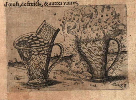
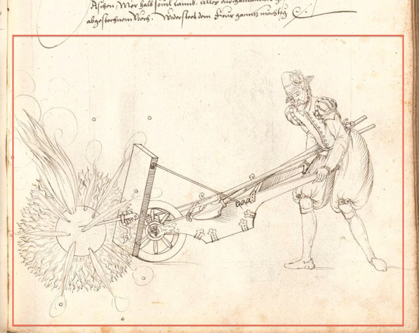
This diagram below from about 1630, shows a clear representation of a booby trap with a basket of attractive objects , within which is a firing lock tied to one of the top objects – lift the attractive object, pull the cord and the firing lock will cause the device to explode. Look carefully and you’ll see the lock at the bottom.

In 1645 we have this description of two IEDs, each clearly using a firearm lock attached to clocks.

In 1650 we have this device, using a pistol firearm lock, initiated by the pull of a string.

In 1764 we have a postal device that utilised a booby trap using a firearm lock.

In 1776 and 1777 The American revolutionaries used systems that instinct suggests to me were similar to Drebbel’s devices of 1628, but develped by David Bushnell. Buchnell also followed Drebbels lead in submarine vessel ideas.

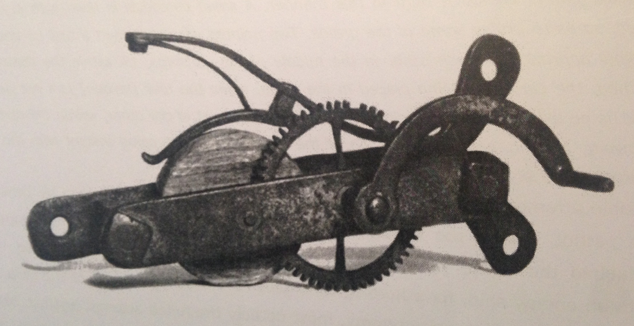
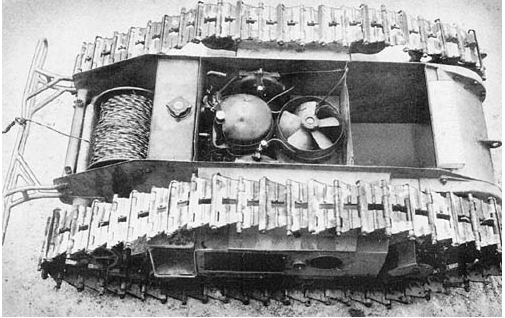
Here’s part of the timing mechanism that Bushnells famous “Turtle” submarine was meant to fasten to the bottom of HMS Eagle. The timing mechanism’s gears ultimately tripped a flintlock mechanism to fire a gunpowder charge. (Photo John Wideman)

Bushnell also used floating explosive charges with levers on the outside designed to be pulled when they came into contact with ships, very much like Drebbels devices of 1628.

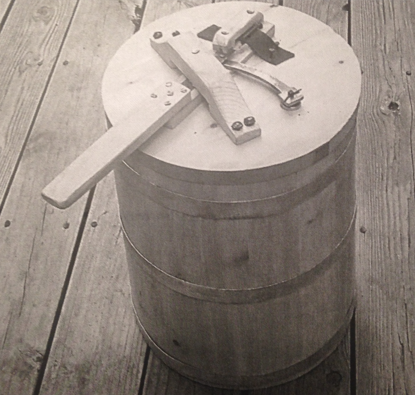
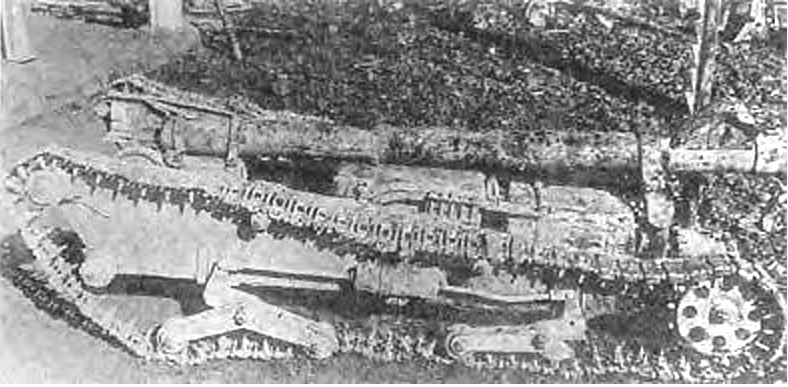
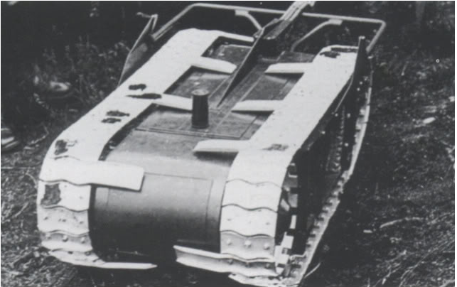
This image is a replica of a Bushnell IED that was floated down a river towards the British ships. The lever on the outside causes a flintlock on the inside lid of the barrel to be activated when the external lever comes into contact with the side of a ship, or a cable is pulled in some manner.

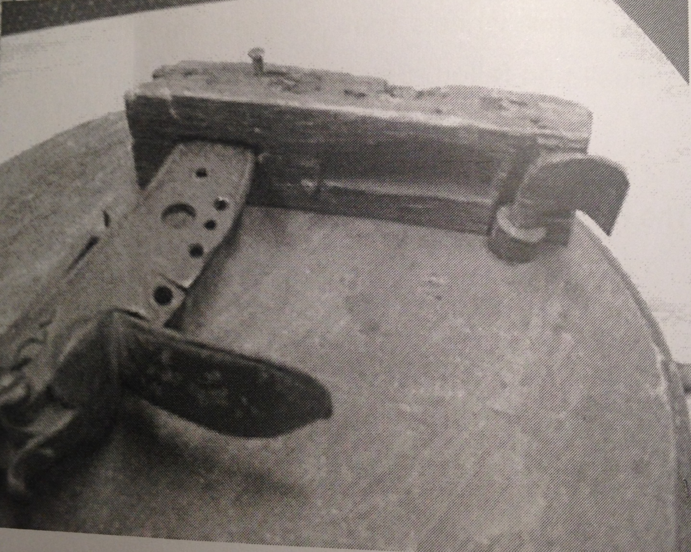
This image below is of an original revolutionary IED, the inside of the lid of the barrel, showing the flint lock mechanism held in place, to be activated by the lever on the outside. The flintlock shown appears to be from a British made “Brown Bess”.

(My thanks to John Wideman for allowing me to reproduce these images from his book “Civil War Torpedoes” where these pictures provide context for his very detailed and excellent work of later devices.)

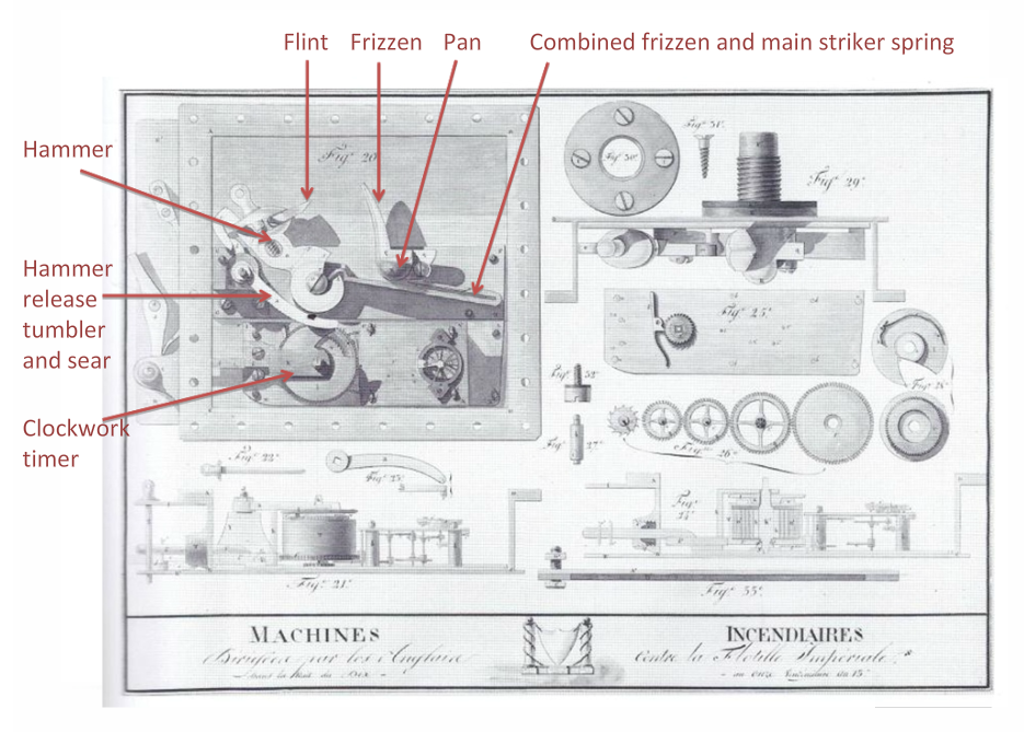
In 1805 Robert Fulton, an American working for the British Navy, (after being rejected by the French) designed a range of explosive devices using gun lock initiators. This diagram, produced by French technical investigators who captured and defused at least one of the devices following an attack on St Malo, shows clearly the firing lock mechanism adapted by Fulton as the explosive initiator. This diagram is one of my best finds.  This is a very sophisticated device and a very sophisticated technical exploitation of the device by the French. The red annotations are mine, part of a lecture I give on historical technical exploitation.

In 1812, during the war with the British, Robert Fulton (who switched sides again, back to his mother country) used gun locks in a number of attacks using explosive devices on the British.  This attack on HMS Ramillies which was blockading American ports, used a very simple device, and nbot one of Fulton’s designs, but nonetheless used firing lock.  It is described by Benjamin Lossing (thanks again to John Wideman for finding this)

In the hold of the schooner Eagle, John Scudder, junior, the originator of the plot placed ten kegs of gunpowder , with a quantity of sulphur mixed with it, in a strong cask, and surrounded it with huge stones and other missiles, which in the event of an explosion might inflict great injury.  At the head of the casks, on the inside, were fixed two gun locks with cords fastened to their triggers at one end and two barrels of flour at the other end, s that when the flour should be removed the locks would be sprung, the powder ignited and the terrible mine exploded. Thus prepared, with a cargo of flour and naval stores over the concealed mine, the Eagle sailed … . she was captured as expected and desired by armed men sent out on boats from the Ramillies.  The crew of the Eagle escaped to the shore at Millstone Point, and anxiously awaited the result. The wind had fallen and for two hours unavailing efforts were made to get the Eagle alongside the Ramillies for the purposes of transferring the cargo to that vessel. Finally boats were sent out as lighters, the hatches of the Eagle were opened and when the first barrel of flour was removed the explosion took place.  A column of fire shot up into the air a full nine hundred feet  and a shower of pitch and tar fell upon the deck of the Ramillies . The schooner, and the first Lieutenant and ten men from the flag-ship on board of her , were blown into atoms and most of those in the boats outside were seriously and some fatally wounded.

Although not involving flintlocks I have details of Fenian IEDs using high explosive initiated by pistols connected to timers in the 1870s, and Lawrence of Arabia’s railway IEDs in WW1 were initiated by adapted martini rifles firing mechanisms – which themselves were an idea copied from the Boers in South Africa in the Boer war.  However all these latter devices were in one sense different – they each actually fired a bullet into high explosive rather than igniting low explosive gunpowder.

I am by no means saying that every IED between 1540 and WW1 used gun locks – but gun locks enabled a simple and reliable way of initiating explosive charges and were used frequently and quite widely during the period.  A gunlock could be used easily to initiate a device, by those three key ways – by command, by the victim or by timer. A gunlock enables concealment and surprise.  I think these facts are crucial to an understanding of how IEDs were used in history.

TECHINT and Radio Controlled Bombs

Follow this link here, to a post I have put on another site, but which readers of this blog with an EOD or ECM background I think will find interesting.

Rockets – a reassessment, a mystery and a discovery

In my recent posts about the Irish rebellion in 1803, I suggested that the crucial development seen at the end of the 1700s and early 1800s was the introduction of a metal rocket casing to increase the internal pressure and hence range of the rockets.   This assessment is stated as a fact in a number of sources, discussing the development of Congreve’s rockets and their metal bodies. I also assumed that the reports suggesting that it was Emmet’s rockets that were a new development and inspired Congreve were right.   There are many historical textbooks which suggest that the designs that emerged in the first few years of the 1800’s were significant developments from the Indian rockets of Tipu Sultan the Indian leader of the Mysore wars. Well, it seems the textbooks, and I were wrong, but in finding this out I encountered something remarkable.  Bear with me as I tell the tale.

Firstly, read my last post about how Emmet in Dublin 1803 manufactured his newly invented rockets. Note that the rockets were described as being two and a half inches in diameter, how the maker, Johnstone “consulted a scientific work respecting the way such materials should be prepared” and that “An iron needle was placed in the centre of the tube around which the mortar was tempered, and when the needle was drawn out, the hole was filled with powder”. Also it describes Johnstone using the written instructions which gave the number of blows used to tap the rocket propellant into place with a mallet.

I then went searching for more historical documents relating to rocket development, and found a copy of this document, dated 1696, a hundred and seven years prior to the Dublin rebellion. This is a book written by Robert Anderson, a researcher in ordnance and artillery working for the Earl of Romney, then “Master General of his majesties Ordnance”. All of a sudden things got interesting very quickly.

On page A4 of the document, here, it says halfway down, “I have given easie, plain and ready Rules for making of Rockets to two Inches and half diameter.

I sat up. Two and a half inches? Could that be a coincidence? I dived deeper.

The book first describes how to make the rocket motor moulds.  Then on page B2 it describes “the bottom of the Rocket-Mould with the Needle to be put in and taken out:”

Then on page B3 it describes filling the rocket composition with charges and tapping the charges into place “and to every Charge  10, 12 or 14 blows with a Mallet”

So, it is very clear to me that Emmet and his rebels were not making newly developed rockets, learned from the experience of the East India Company’s battles against Tipu Sultan – they were making rockets to the specific design of a two and a half inch rocket design of Englishman Robert Anderson, written over a hundred years earlier in 1696, and using the same document I have in front of me now.  Remarkable.  I’m not aware of anyone realising that link before now.

I then went a couple of pages further on and found this diagram. The adjoining text clearly states that the rocket body (AFEB) is made from a piece of gun barrel, and is metal, not pasteboard. Thus the English (and Anderson specifically) had already designed metal rocket bodies over a hundred years before Emmet and subsequently Congreve used the same concept. Many references (incluidng Encyclopaedia Britannica and Wikipaedia) have this wrong ascribing such development to Tipu Sultan a hundred years later.

So, I think this changes our view of history. Emmets’s rockets were not his own development – they were explicitly built from instructions from an English developer over a hundred years old by 1803. Also, Congreve’s rockets were not new in using metal bodies to increase the internal pressure of the rocket motor – that too was achieved by the same developer, Anderson in 1696.

I find it fascinating that rebels today are making their own versions of these munitions, in hidden rooms in Syria, 300 years since Anderson, and 200 years since Emmet copied his designs, constructed them in hidden rooms in Dublin and first used them in a rebellion. Of course today’s rockets have changes in design and in the rocket composition – but in effect, frankly, they are pretty darned similar.

Inventing Detonators

I’m intrigued by the chain of historical inventions that led to the modern detonator.

Detonators for explosive charges evolved from firearm trigger mechanisms and I see these as an invention continuum, with one leading to another. Alongside these mechanical inventions, chemical discovery runs as a parallel track, particularly the discovery or primary explosives and high explosives, which detonate by shock (gunpowder being a low explosive which explodes by deflagration)

Initially, I guess the first “initiators” were simply burning fuzes which transmitted a flame to gunpowder. However there is some early mention of a some victim operated mechanisms perhaps using friction devices or steel and flint levers.   See Chinese IEDs here.  

To help undertsand the chain of scientific, chemical, physical and mechanical inventions that took us down this path the folloing rough time line might be useful:

Pre 1400 – Burning fuzes of various types, igniting gunpowder by burning.

Early to mid Mid 1400s – Invention of the matchlock mechanism to initiate firearms. Note that this was definitely a European invention – the Portuguese took matchlocks and introduced them to China and Japan.  (The story of how the Japanese obtained and reverse engineered the matchlock will be the subject of a future post) .

About 1500 – Invention of the wheel-lock, possibly by Leonardo Da Vinci, which introduces a new mechanical action to apply a burning fuze to a specific point.

1540 – The snaplock was invented, using a flint initiator. This was a precursor to the more sophisticated flintlock

1558 – The snaphaunce was developed which incorporated a mechanism for keeping the gunpowder covered until the flint fell, when the cover is opened automatically.  The cover is called the frizzen.

1588, a time initiated system used by Giambelli to explode the “Hoop”, with a timing mechanism causing ((I’m guessing with a snaplock or snaphance) to initiate the charge.

1602  Gold fulminate (the first primary/high explosive) discovered by John Tholde of Hesse.

1610 – The first flintlock initiation system developed The flintlock mechanism is an evolution of the snaphaunce whereby the frizzen is not only a cover for the pan of gunpowder, but also the steel face on which the flint strikes to cause sparks.

1659 Robert Hooke and Thomas Willis discover the primary explosive characteristic of Gold hydrazide

1745  Dr Watson of the Royal Society showed that an electrical spark from a Leyden jar could initiate a small blackpowder charge.

1750  Benjamin Franklin initiates gunpowder with an electrical spark and makes small paper tubes of  powder with two wires inserted and a spark gap created.

1788  Silver fulminate was first made by French chemist Berthollet.

1776 – American revolutionaries used adapted firearm mechanism to make contact mines consisting of “kegs” of gunpowder which were floated down rivers.  The kegs have fastened to the lid a wooden arm which when it touched a target ship connected to an iron pin, engaging a flintlock device from an adapted firearm, causing the main charge to explode.  Note the similarities in principle to much later IED initiators here.  I’ll post some images of these “kegs’ in future posts.

1777 – Italian scientist Alesandro Volta, describes how he had fired pistols, muskets and a ”mine subacquee” (underwater mine) electrically – it appears he used a hot wire to initiate a glass bulb full of a flammable gas.

1782 – Another Italian scientist, Cavallo, described detonation of a charge of gunpowder, electrically, using an incandescent wire embedded in the powder

1795 – Cavallo uses another method, using gunpowder mixed with steel filings, with two electrical probes embedded in it.

1799 – Fulminate of mercury, a primary explosive later used in detonators was first prepared by Charles Howard. Interesting reports on his experiments are here and I think its very significant indeed that Howard actually tested electrical initiation of mercury fulminate. I note also that Howard refers to French scientists electrically initiating some form of potassium chloride based explosive in the late 1700s.  Howard’s description of the experiments he conducted with mercury fulminate are fascinating – clearly he hoped he had invented an alternative to gunpowder, but initiating mercury fulminate within a gun caused some catastrophic damage to his equipment!  There is a great description of how Howard measured the volume of gas produced from a specific quantity of the explosive.

1812 – The Russian military scientist Pavel Schilling developed an electrically initiated IED, as a mine.  My apologies, in earlier posts I credited this to others later in the 19th Century, and I have only recently discovered Schilling’s  (and Volta’s, and Howard’s) technologies.  Schilling gradually improved the associated technologies, insulating wire with tarred hemp and copper tubing, and devising a carbon arc initiator.

Also in 1812 – Prussian scientist Sommerring improved the insulation of electrical wire, using rubber and varnish, allowing further capabilities to be developed in initiating explosives.

1820 – American scientist Robert Hare, worked on electrical initiation of flammable gases. Hare also developed a “plunger” type galvanic machine for producing electrical charges for this purpose.

1822 – Hare used  a hotwire embedded in a pyrotechnic mixture to initiate a blackpowder charge.  In the 1830s Hare also produced a tin tube container packed with powder and with an ignition wire for rock blasting but foresaw the military importance of command initiated explosive charges.

1829 – A young Samuel Colt initiated an under water charge electrically perhaps using a tarred copper wire.

1831 – The Bickford burning fuze was invented, taking away the guess work about time delays for burning fuses.

1837  Colonel (later General) Pasley of the Royal Engineers developed chemical then an electrical initiation mechanism to explode gunpowder charges under water. Pasley’s work appears to have been prompted by reading a  newspaper report of an “ordnance accident”, in Russia, when Tsar Nicholas I narrowly escaped death when viewing a demonstration of electrically initiated gunpowder charges used to blow up a bridge, presumably developed by Schilling. Pasley read the article and then sought the advice of English scientist Charles Wheatstone to consider how he might use the same concept.  Pasley’s contributions to military engineering are huge, and his explosive related inventions are very significant if only a part of that broader work.  I have yet to find details of Pasley’s chemical fuzes, but his electrical initiation mechanisms used electrically heated platinum wire, with the electricity provided by early galvanic cells. Pasley solved the problem of insulating the wires so they could be used under water, by coating wire with gutta percha. The platinum wire (or foil) provided enough heat to initiate the gunpowder it was embedded in.  However some reports state that the electrical system caused a detonation by a “galvanic spark” so the actual mechanism is still a little unclear.   I’m very intrigued by the chemical fuzes and how they worked, given the nature of the underwater tasks that Pasley developed the explosives for. I think it likely that there would have been some form of command pull to initiate the chemical reaction once the divers were clear and safe.  Chemically the reaction may have been similar to Nobel’s (later? ) designs.

1830s  –  Immanuel Nobel developed chemical initiation mechanisms to initiate gunpowder. The mechanisms used a glass vial containing suplhuric acid, which when broken (usually by an enemy) caused the acid to fall by gravity onto potassium chlorate, which ignited and caused surrounding gunpowder to initiate. These were confusingly called “Jacobi” fuzes after the Russian scientist for whom Nobel worked.  Jacobi led the Russian “armed services committee for underwater experiments” between 1839 and 1856. It is clear that Jacobi’s secrecy prevented international publication of the scientific achievements he made in electrical initiation. Jacobi’s work  from 1839 seems to have been prompted by both Schilling and Pasley.  What is significant is a reference I have found to Jacobi developing “mercury connecting devices” which probably mean some form of mercury electrical switch to initiate contact mines in the 1850s.

1830s, Mercury fulminate was used in copper caps used as firearm initiators taking the place of flint, and making the process of initiating a firearm much less dependent on flint and the weather.

1839 – Other British Royal Engineer salvage operations in Bermuda and in Bengal on the Hoogly river used electrically initiated charges.  I have a great piece of reseacrh to blog about with regard to the Hoogly river operation.

1840s – Samuel Colt conducted extensive work on highly complex electrical initiation systems for sea and river mines.

1848 – Werner von Siemens developed electrically initiated sea mines.

1863 – Alfred Nobel (Immanuel Nobel’s son) published his patent for a practical detonator to initiate nitro-glycerine.  Note that this was four years before his patent for dynamite.  In modern parlance this was a non electric blasting cap, itself initiated with burning fuse.   The detonator consisted of a small blackpowder charge, a wooden plug and a small quantity of nitroglycerine held within a metal cylinder. The black powder is initiated by a burning fuze, which pushes the wooden plug down the cylinder, which then strikes the niroglycerine with kinetic energy.

1865 –  Nobel refined his detonator design significantly, with a small metal tube containing mercury fulminate

1868. H. Julius Smith produces a detonator that uses a spark gap and mercury fulminate.

1875 The electrical detonator using a hot filament was developed independently by Gardiner and Smith

Close Me
Looking for Something?
Search:
Post Categories: